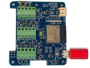
 For this troubleshooting guide we suggest you power the ADC HAT by connecting a USB power adapter to the micro-USB connector. Follow this link to get a high quality USB Power adapter: https://www.amazon.com/Seenov-Supply-Adapter-Raspberry-Tablets/dp/B0B1F5XXFD/
There is no power LED but we will introduce a blinking pattern to show power is OK in the near future.
The USB port is for power only, if connected to a PC, the ADC will not be detected as a new USB device.
It is not recommended to power the ADC from programming connector since the serial converter may not be able to supply enough current.
Do not power the ADC from the programming connector and one of the other power sources at the same time.
 There are no I/O connections between the ADC HAT and the Raspberry Pi. No RS232, no I2C, no SPI. All communications are done over WiFi using a UDP channel.
LED D1 (green on some boards)
Before any communication can occur, the ADC HAT must connect to your WiFi network. After power is applied it tries to connect to the WiFi network programmed into its non-volatile memory (eeprom). It will try for up to 60 seconds.
Out of the box, the eeprom is blank so nothing will happen for 60 seconds. After 60 seconds, if it was unable to connect, the LED D1 will turn on. Follow the instruction in the video “5 steps to success”, link: https://www.youtube.com/watch?v=d51QhskOLHE ,
to enter the SSID and Password of your WiFi network.
Once that is done, the ADC HAT will reboot and LED D1 will turn off. Wait 60 seconds.
What if LED D1 turns on again?
This indicates the WiFi credentials that were entered, were wrong (caps lock enabled, typo, misspelling etc) or the WiFi is out of range. Since the ADC HAT is unable to connect, it will restart the process to enter the SSID and Password, re-enter the SSID and password.
The LED D1 turns off and stays off.
Success, the ADC HAT is connected to your WiFi network and it is waiting for a UDP message to start analog to digital conversions. We will introduce a blinking pattern to indicate this state in the future. At this stage, you can communicate with the ADC using our Node-Red flow running on a Raspberry Pi or any other computer, that is on the same network, running Node-Red. Follow the instruction in the video “5 steps to success”, link: YouTube Seenov Channel
Talking to the ADC HAT using Node-Red
Make sure you watch the second video “Installing Node Red on the RPi to control the ADC” https://youtu.be/GfMtT9EnXfo
Watch This Video First![]() When you press the find button in the Node-Red dashboard, there are a few specific things that happen to initiate communications. Fist Node-Red must find the IP address of the computer it is running on. Then it must find the broadcast address for the network it is connected to and use it to send out a broadcast message that all devices on the network, including the ADC HAT, will receive.
When you press the find button in the Node-Red dashboard, there are a few specific things that happen to initiate communications. Fist Node-Red must find the IP address of the computer it is running on. Then it must find the broadcast address for the network it is connected to and use it to send out a broadcast message that all devices on the network, including the ADC HAT, will receive.
The most common problem is Node-Red is sending messages using wrong IP address.
If the ADC is not found it could be because Node-Red did not find the correct broadcast address.
The code in the ”Set broadcast IP” function node finds this broadcast address. Check that line 15 is commented out and try the Find button again.
Make sure the green debug node named “Second” is connected to the first output of the node “Set Broadcast IP”. Click the Debug icon at the top of the right column. Clear all messages. Go to the dashboard and click the “Find” button. Back in the debug column search for the IP of the message sent over the network.
 Broadcast messages are sent on the last IP of the network. If your network is 192.168.0.0 mask 255.255.255.0, the broadcast is 192.168.0.255. If you Network is 192.168.34.0 mask 255.255.255.0 then it is 192.168.34.255. Your network settings can be found in your Router configuration page.
If the you are still unable to talk to the ADC HAT contact us for support with the link at the end of this post. Send as much information as possible. We will respond as quickly as possible.

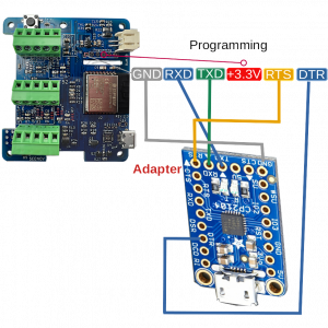
This is the second way to communicate with the ADC. This port enables you to monitor the ADC HAT’s status and reprogram it.
Make sure the adapter is set to 3.3 Volts.
Connect the RXD, TXD, DTR, RTS, GND pins as shown in the picture on the right.
The code sends out many status messages during the first 20 seconds after reset. Once this delay has passed, less frequent messages are sent to the serial port. The baud rate is: 115200. The code is fully commented. You may want to look through it. We use Arduino to compile the code. You can also use Visual Studio Code to compile the code. Before attempting to program the ADC HAT see the Espressif ESP-IDF Programming guide. Link : https://docs.espressif.com/projects/esp-idf/en/latest/esp32c3/get-started/index.html#software
If the you are still unable to talk to the ADC HAT contact us for support with the form at the end of this post. Send as much information as possible. We will respond as quickly as possible.


