New Python User Interface
You will need a Raspberry Pi or any other computer running Python 3 to remotely control the ADC with the user interface.
We have tested the Python script on a Raspberry Pi 400, a MAC, a Linux Mint computer and of course a Windows 10 machine.
This new UI was created with Python and CustomTKinter.
Installing the New User Interface On Your Computer
We have created a folder with the UI files and the CustomTKinter app.
Go to our GitHub repository and download the content of this folder. Run the Python script: ADC_UI_Beta1.py
On Linux: in a terminal window type: python3 ADC_UI_Beta1.py
On Windows: Install Python 3. You can find excellent Youtube videos showing how to install python 3 such as this one.
On MAC: Install Python 3. You can find excellent Youtube videos showing how to install python 3 such as this one.
You should see the GUI appear. The script will automatically search for the ADC and once it has found it, it will start displaying the values for all the channels in mV if it is connected to your network. Read the next section to find out how to connect your 6 Channel ADC HAT for Raspberry Pi to your network.
The switches on the left enable or disable individual channels. Each enabled channel performs an A to D conversion sequentially. The more there are enabled channels, the slower the conversion rate. The conversion rate is controlled by the right slider. The rate is the delay in mSec between conversions for all enabled channels. The default rate is 127 mSec. Every 127 mSec all channels are converted.
WiFi Communications with the User Interface

The first thing the RESP32C3 ADC does, after booting up, is to try to connect to a WiFi network. If it cannot connect, it will turn itself into a Hot-Spot (Access-Point). A green LED will turn on on the board.
Using a smartphone or a WiFi enabled device, find the network called ADC_xxyyzz ( xxyyzz are the ESP32C3’s 3 last mac address digits) and connect to it (no security password required). Ignore any “No Internet” messages.
Open the smart phone’s web browser and go to page 192.168.4.1 and enter your networks SSID and Password. The ESP32C3 ADC will now connect to your network and listens on UDP port 5044 while transmitting to the Raspberry Pi on UDP port 5045.
Programming
The ESP32C3 ADC sketch was developed using Arduino 1.8.19. Arduino 2 has not been tested yet.
There are 2 ways to program the ESP32C3 ADC.
The first is using to OTA function. create and test your software and save the output .bin file where you can find it. Go to the Python dashboard and press the OTA button. With a web browser go to http://esp32c3_adc.local page. The user and password are: admin admin. You will be directed to select a .bin file and start the update. Once to update is completed, the ESP32C3 ADC will reboot and start the new firmware. IMPORTANT: You must include the OTA functionality in your code or future over-the-air updates will not be possible.
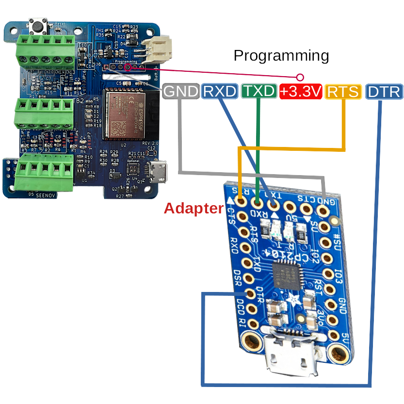
The second way is to use a USB to serial converter and connect it to the programming header. Note that some USB to serial converters cannot provide enough power for the ADC board.
IMPORTANT: TxD of the ADC is connected to RxD of the adapter and RxD of the ADC is connected to TxD of the adapter.
Connect the serial to USB adapter as shown below:

Description
The ESP32C3 6 channel ADC is a flying hat for the Raspberry Pi family of boards. Flying means it can be disconnected from The Raspberry Pi and placed anywhere within WiFi range. Since it can be seperate from the Raspberry Pi, it is the perfect hat for your RPi 400. Th 12 bit ADC has a factory calibration that enables it to reach a precision in the range of 1 to 2%. In addition an on-board 1.25V reference can be used to further increase the accuracy. All Raspberry Pi GPIO pins are free for other uses, the ESP32C3 communicates wirelessly with the RPi over a UDP WiFi channel. A Python User Interface simplifies the control of your ADC.
Additional resources on the ADC board include:
- 3 GPIO (outputs by default) can be reprogrammed to any functions supported by the ESP32C3 (In/Out/I2C/Serial/PWM
- One buffered DAC output with a default resolution of 8 bits.
- A battery interface.
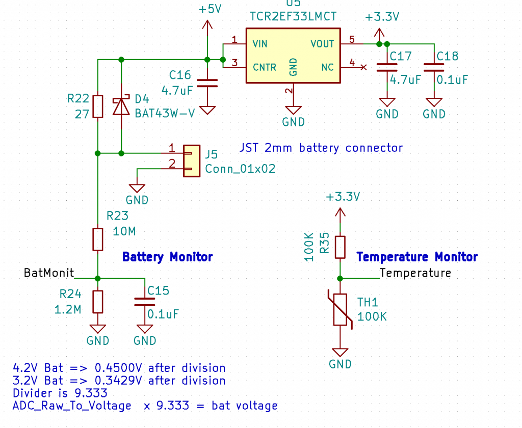
- A resistor divider to measure battery voltage.
- A thermistor to measure temperature.
- A reset button.
- 2 user LEDs
- 4 power sources.
- Over-The-Air (OTA) firmware upgrade.
The ESP32C3 ADC hat comes with a pre-installed Arduino sketch that provides basic functionality. It is designed to auto connect with a Node-Red flow running on the Raspberry Pi. The software features include:
- Use of factory calibration to correct the raw ADC data on all channels.
- Average of 16 samples per ADC channel to eliminate noise.
- Programmable delay between sample bursts.
- Auto Hot-Spot to enter WiFi credentials if the WiFi connection fails.
- WiFi SSID and Password saved in EEPROM.
- Auto connect to the Node-Red flow.
- Auto reporting of ADC channel values.
- Over-The-Air firmware updates.
- UPD communications.
Power
The ESP32C3 6 channel ADC ha 4 possible power source.

- Raspberry Pi +5V and ground on the 40 pin connector. Pass-through headers are provided in the kit for these pins and the adjacent ones. This power source also charges the battery.
- A power only USB connector. This power source also charges the battery.
- A Lithium-Polymer battery connector. The maximum charging current is 74mA, rapidly diminishing as the battery voltage rises. Only batteries with integrated protection circuitry can be connected to this port.
- Power from the programming connector. Pin 4 of this connector accepts +3.3V. If power is connected to this pin, all other power source must be disconnected. The ESP32C3 can have bursts of over 300mA when transmitting. Some USB to serial converters cannot supply such current.
Inputs and Outputs

Battery and Temperature Measurements
 To measure the battery voltage place a jumper between the BAT and the CH2_0 terminals. Multiply the results by 9.333 to obtain the battery voltage.
To measure the temperature, place the jumper between the C° and Ch2.0 terminals.
The thermistor’s characteristics are:
NTCG164LH104HTDS Electrical Characteristics
| Resistance [at 25°C] |
|
| Resistance Tolerance |
|
| B value (Typ.) [25/50°C] |
|
| B value (Typ.) [25/85°C] |
|
| B value (Typ.) [25/100°C] |
|
| B value Tolerance |
|
| Max. Electric Power [at 25°C] ? |
|
| Permissive Operating Current [at 25°C] ? |
|
| Thermal Dissipation Constant [at 25°C] ? |
|
The Rth1( thermistor) value= (Vch2.0 x 100K) / (3.3V – Vch2.0)
The temperature can be calculated as follows:
float temperature;
#DEFINE R0 100000 // 100K
#DEFINE B0 4485 // up to 50C
temperature = Rth1 / R0; // (R/Ro)
temperature = log(temperature); // ln(R/Ro)
temperature /= B0; // 1/B0 * ln(R/Ro)
temperature += 1.0 / (25 + 273.15); // + (1/To) in kelvin
temperature = 1.0 / temperature; // Invert
temperature -= 273.15; // convert Kelvin temp to C
ADC2.0 can be used for other measurements its range is 0 to 2.5V. it cannot be configured for bipolar or higher voltages as are the ADc1 channels.
Note: ADC2.0 is sampled 16 times before the average is calculated. By default this takes 2:40 minutes.
ADC1 Channels 0 to 4
By default, these channels have a 10nF input filter capacitor and can accept a voltage of 0 to 2.5V.
Many possible configuration of these inputs are possible. Please see this link for a detailed explanation.
1.25V Reference
The reference can be used to power sensors or to re-calibrate any of the ADC channels. Note that there is a 82 ohms resistor in series with the output to protect against static discharges.
DAC
GPIO6 of the ESP32C3 is buffered and filtered by an Op-Amp. By default, the 8 bit AnalogWrite function is enabled on this output. Higher resolutions are possible.
GPIO 7 – 18 -19 LEDs
These are programmed as regular outputs. They can be re programmed with other functions. Two LEDs are defines as LED and LED2.

